Rechargeable Battery Based on Substituted LS Polyanilines
by
M.K. Ram*, M. Adami*,
M. Sartore*,
M Salerno*, S.
Paddeu‡ and C.
Nicolini ‡,+
*Polo Nazionale Bioelettronica,
Parco Scientifico-Technologie dell'Elba - 57030,
Via Roma -28, Marciana (LI) Italy
‡Elba Foundation, Via A. Moro
15, 57033,
Marciana Marina (LI), Italy and
+Institute of Biophysics,
University of Genoa,
Via Giotto 2, 16153, GE. Sestri Ponente, Italy |
This is a draft paper
for a talk at the
Fifth
Foresight Conference on Molecular Nanotechnology.
The final version has been submitted
for publication in the special Conference issue of Nanotechnology.
This page uses the HTML <sup> and
<sub> conventions for superscripts and subscripts. If
"103" looks the same as "103"
then your browser does not support superscripts. If "xi"
looks the same as "xi" then your browser does not
support subscripts. Failure to support superscripts or
subscripts can lead to confusion in the following text,
particularly in interpreting exponents.
Abstract
Ultra thin films of polyaniline (PANI), poly(o-toluidine)
(POT), poly(o-anisidine) (POAS) and poly(ethoxy aniline) (PEOA)
were engineered by Langmuir Schaefer (LS) technique. It was shown
that the effect of substituent groups plays a prominent role for
the fabrication of ultra thin films. In this regards, Langmuir
isotherm of the PANI, POT, POAS and PEOA were investigated at
aqueous subphase of pH 1, where doping during the monolayer
formation appeared as an essential step for the high quality of
Langmuir film. The area per unit molecule was shown to increase
by increment of the substituent groups in polyanilines. The
deposited LS films of such polyanilines were characterized by
cyclic voltammetry. The electrical properties of polyanilines
were studied depositing on interdigited electrode. The uniformity
in each deposition was verified by atomic force microscopy (AFM).
In this communication, the main objective is to report on the
existing link between optimization of the above properties and
the charging/discharging properties of substituted polyanilines
LS films towards the optimal manufacturing of a rechargeable
battery based on this class of conducting polymer.
1. Introduction
Polyanilines have received great attention due to their
environmental stability, ease in preparation, exciting
electrochemical, optical and electrical properties [1-3].
Polyanilines have also been postulated as a potential candidate
for numerous electronic applications such as electrochromic
displays, rechargeable batteries, microelectronics devices,
biosensors, protective coating and chemical sensors [4, 5]. For
many device application, it is desirable to have polyanilines in
a thin films structure, preferably with known thickness and
molecular packing [5]. Langmuir-Blodgett (LB) films offers the
unique control over the film architecture, thickness and
molecular orientation [6, 7]. Recently, LB films of polyaniline
have been obtained by exploiting the solubility of polyaniline in
N-methyl 2-pyrrolidinone (NMP)/CHCl3 mixture [8-10].
It is to be noted that even if polyaniline is not a typical
amphiphilic molecule, still stable monolayer of polyaniline have
been obtained and subsequently transferred as LB films [11]. The
stability of monolayer has been seen improving for the
substituted polyanilines [12, 13]. The effect of substituents
group (-CH3, -OCH3 or -OC2H5
etc.) in monomer or polymeric chain of polyanilines appears to
enhance such potentiality, by displaying at the same time a
significant increase in electronic localisation with simultaneous
decrease in conductivity but an excellent solubility in a number
of organic solvents. The solubility of polyanilines enables to
assemble such conducting polymers into ultrathin films at the
molecular level with high degree of order [14-17]. However, the
comparative studies of the fabrication for various types of
polyanilines LS films is not shown in literature.
The influence of different subphase condition on the pressure
(P) -Area (A) isotherm of polyanilines plays an important role
for the stable Langmuir monolayer [18, 19, 20]. In our earlier
investigation, we had shown the effect of subphase (maintaining
at different pH value) on the orientation of poly(o-anisidine)
(POAS) molecules at air/water interface [18]. POAS showed a
decrease in area/molecule when Langmuir monolayer was fabricated
at pH ranging from 6.4 to 1. In particular, we focused our
attention on the effect of the polymer doping upon the Langmuir
monolayer and LB film fabrication for various polyanilines.
With these consideration, we used various types of
polyanilines, i.e. polyaniline (PANI), poly(o-anisidine) (POAS),
poly(o-toluidine) (POT) and poly(o-ethoxy aniline) (PEOA). The
effect of substituents on polyanilines can be observed in the
fabrication of Langmuir monolayers at different aqueous
subphases. The deposited LB films were examined using cyclic
voltammetry in HCl media in order to assess the redox
characteristics of various polyanilines at an identical
condition. The surface morphology as well as the uniformity of
polyanilines LS films were investigated by Atomic Force
Microscopy. The current (I) -voltage (V) characteristics of
polyanilines were measured deposited on interdigited electrodes.
The charging and discharging effects of polyanilines were studied
for their application in rechargeable batteries.
2. Experimental Section
2.1 Synthesis of POAS conducting polymer
The monomer aniline, ortho-toluidine, ortho-anisidine and
ortho-ethoxy aniline, oxidizing agents and various reagents were
obtained from Sigma for the synthesis of various polyanilines.
Polyanilines were chemically synthesized by oxidative
polymerization of monomer using ammonium perdisulphate [(NH4)2S2O8)]
under controlled conditions [19, 21, 22]. 0.215, 0.215, 0.219 and
0.220 M of distilled aniline, toluidine, o-anisidine and o-ethoxy
aniline were used separately for the synthesis of polyaniline
(PANI), poly(o-toluidine) (POT), poly(o-anisidine) (POAS) and
poly(o-ethoxy aniline) (PEOA), respectively. Each monomer was
added slowly in a 200 ml solution of HCl containing 0.05M (11.5
gm) ammonium perdisulphate precooled to 4�C in an ice bath. The
reaction was continued for 12 hours. The dark green precipitate
of each polyanilines recovered from the reaction vessel, was
filtered and washed by using 1M HCl to remove the oxidant and
oligomers. This precipitate was subsequently washed by deionized
water (for several times), methanol and diethyl ether to remove
the low molecular weight polymers as well as oligomers (violet in
colour). The emeraldine form of each polyanilines was heated at
100�C. The green powder thus obtained was the emeraldine salt
(ES). Such ES of each polyanilines was subsequently treated by
using aqueous ammonia for 24 hours. Further, each emeraldine base
(EB) form of each polyanilines was washed in distilled water and
acetone for several times and then, dried for 6 hours at a
temperature of 100�C. It should be noted that poly(o-anisidine)
and the poly(o-ethoxy aniline) were washed by using acetone
during the synthesis, which is very similar to the preparation of
polyaniline because of the removal of low molecular weight
polymers and oligomers [19]. It was found that POT, POAS and PEOA
were soluble in chloroform. The powder thus obtained was
emeraldine base (dark blue in colour) of each polyanilines. The
precipitation of POT occurred in one or two days, while POAS and
PEOA did not show any precipitation for a prolonged periods.
2.2 Formation of polyanilines LS film.
The polyaniline solution for the fabrication of LS films was
prepared by using stabilizer such as N-methyl pyrrolidinione
(NMP) but the subsituted polyanilines were simply dissolved in
chloroform. A stock solution was prepared by dissolving 5 mg of
polyaniline in 2 ml of NMP and 20 ml of CHCl3 for
immediate use. The resulting solution was filtered with solvent
resistant filter (0.5l ). The 0.2 mg/l solution of each POT, POAS
and PEOA polyanilines were made in CHCl3 and 100 -150
�l of solution was spread onto two types of aqueous subphases,
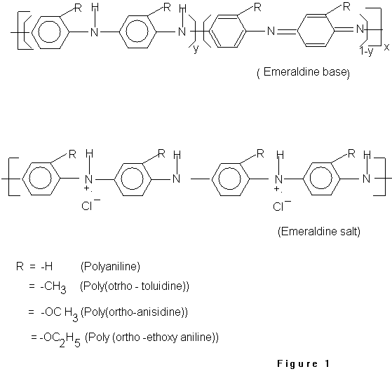
i.e., pH 1 using HCl and deionised water. Fig.1
shows the general structure of polyanilines conducting polymer,
where y = 1/2, 1 & 0 give rise to emeraldine, leucoemeraldine
and pernigraniline form, respectively. Fig.1 also shows the doped
form of each polyanilines. After the isotherms were recorded, it
appeared that the film formed at pH 1 showed higher collapse
pressure. So, pH 1 was separately used as subphase for the
deposition of LS films for various polyanilines. LS films were
formed in LB trough, with 240mm x 100 mm in size and 300 ml in
volume (MDT corp., Russia) having a compression speed 1.667
mm/sec. Different number of monolayers were transferred onto
glass, platinum, glass indium-tin-oxide plates and at
interdigited electrode substrates (containing chromium
electrodes, which were cleaned with ethanol and chloroform
previously) by Langmuir-Schaefer technique, respectively. The
stability of the Langmuir monolayers of each polyanilines was
verified at various pressure and later, 20 mN/m, 22 mN/m, 25 mN/m
and 18 mN/m surface pressure was maintained for the deposition of
PANI, POT, POAS and PEOA LS films.
2.3 Atomic force microscopy
The Atomic Force Microscope used was home-built instrument
(Polo Nazionale Bioelettronica) working contact mode [24]. It was
operated in air, at constant deflection (i.e. vertical contact
force) with a triangular shaped gold-coated Si3N4
microlever (commercially available Park Scientific Instrument
chips). The tip of the microlever had standard aspect ratio
(about 1:1) and the lever had nominal force constant of 0.03 N/m.
The constant force set point was about 0.1 nN, while the images
acquired were 128x128 pixels maps. During acquisition the row
scanning frequency was 4 Hz, i.e. a physical tip-sample motion
speed of 8-4-2 micron/sec in the 2-1-0.5 micron scan size images,
respectively. All images are standard top-view topographic maps,
where the brightness is proportional to the quote of the features
over the sample surface, i.e. light means mountain, dark means
valley. Some of the images present high features that were
saturated in the post-processing redistribution of the available
grey levels, because much higher than the most of the data
points. Henceforth, it was possible to observe the finest
structure of the samples. The images shown are representative of
the samples, since images of the same looking appears in 4
different regions of the analyzed samples, positioned at the
vertices of a square of side about 4 mm, centred at the specimen.
2.4 Electrical and Electrochemical measurements.
The electrical characterization was performed using an
electrometer (from Keithley model 6517) as well as
Potentiostat/Galvanostat (EG &G PARC model 163). The
electrochemical measurements were made by
Potentiostat/Galvanostat (from EG & G PARC model 163 with a
software of M270). A standard three electrodes configuration was
used, where LS films on glass ITO plate acted as a working
electrode, platinum as a counter and Ag/AgCl as a reference
electrode. The cyclic voltammograms were measured for 30
monolayers of PANI, POT, POAS and PEOA polyanilines films at 1M
HCl. The charging and discharging experiments on such
polyanilines films were performed at various concentration of 1M
HCl. Further, the charging and discharging of polyanilines were
performed using Al/LiClO4+propylene carbonate(PC)/
polyanilines configuration.
3. Results and discussions
3.1 Pressure -area isotherm
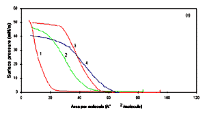
Figure 2a shows the P-A isotherms of
polyanilines in deionized water. The effect of substituents in
polyanilines can be seen while they form the Langmuir monolayers.
The stability of Langmuir monolayer is found to be associated to
a high collapse pressure, a steep increase in the pressure in the
condensed phase for PANI (curve 1), POT (curve 2) and POAS (curve
3), conducting polyanilines. It shows an increase of pressure in
the condensed phase and the yielding (breaking) point for the
pressure has been obtained at a different surface pressures for
each polyanilines. The wrinkles could be observed for the
pressure of 42, 40, 39 and 28 mN/m for PANI (curve 1), POT (curve
2), POAS (curve 3) and PEOA (curve 4), respectively. The PANI
shows higher collapse pressure with respect to other class of
polyanilines (as studied), which may be liked to the NMP (i.e.,
NMP is sparingly soluble in water). Nevertheless, the effect of
substituents in polyanilines could be observed at air/water
interface, which shows the large change in area per molecule at
the condensed phase. For the estimation of molecular area at
condensed phase, one repeating unit of each polyanilines have
been taken into account as shown in Fig.1.
The obtained area per molecule for PANI, POT, POAS and PEOA at
air/water interface estimated using Fig.2a,
were found to be respectively at around 26, 45, 55 and 62 �2
by extrapolating the pressure-area isotherm curves. The cross
sectional area of the aniline repeat unit at air - water
interface has already estimated to be 20 �2 [8].
These results show that substituted polyanilines molecules are
not oriented and occupy larger area at air-water interface than
the repeat unit for each polyanilines [25].
The stability of Langmuir films at air/water interface
according to the subphase is another important issue for the
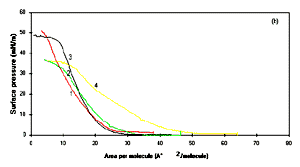
better quality of films [4,5,8,18, 19, 20]. Figure
2b shows the pressure -area isotherms of each substituted
polyanilines at the aqueous subphase maintained at pH 1 using
HCl. The doping appears to be an important factor for the
stability of the monolayers, which is probably associated with
the ordering that is introduced in the polymer at air/water
interface at pH 1. So an attempt has been made for the estimation
of molecular area of substituted polyanilines at air-water
interface by extrapolating the pressure -area isotherm curves
shown in Fig.2b. The area obtained at 1 pH
has been found to be about 20, 25, 21 and 45 �2 for
PANI, POT, POAS and PEOA respectively. The area per molecule for
PANI, POT, POAS supports the concepts that at pH 1, the
emeraldine base form of polyanilines is changed to emeraldine
salt [8]. The bigger value in the area per molecule, found for
the repeat unit molecule of PEOA in curve 4 of Fig.2b, could be
linked to the bulky group (-OC2H5) in each
monomer of PEOA. It can also be speculated that -OC2H5
causes substituted polyaniline to form different structure to
accommodate the side group and possibly not as unfolded similar
to PANI, POT or POAS conducting polymer. The stability of the
films was further checked at different pressure with compression
speed of 1.67 mm/sec for each polyanilines. 20, 22, 25 and 18
mN/m surface pressures were found to be best values for the
deposition pressure for PANI, POT, POAS and PEOA LS films. Such
deposition pressures were also reported in literature [4, 8, 18].
[Full size Figure 2a: 6K, 638 x 356 pixels]
[Full size Figure 2b: 6K, 638 x 356 pixels]
Figure 2a: Pressure -area isotherm of Langmuir
monolayer in deionised water : (1) PANI, (2) POT, (3) POAS
and (4) PEOA. Figure 2b shows the pressure area
isotherm of Langmuir monolayer in aqueous sulphase containing
pH 1 for (1) PANI, (2) POT, (3) POAS and (4) PEOA.
3.2 Atomic force microscopy (AFM)
This technique was used to study the morphology of multilayer
films prepared using different polyanilines LS films. Fig.3 shows AFM images of dimensions 1 x 1 �m
of 15 monolayers for PANI, POT, POAS and PEOA films. The AFM
images of this film reveal a fine grained structure for PANI, POT
and POAS, whereas it shows the extremely fine grain size for
PEOA. Moreover, these images show the uniformity in the
polyanilines LS deposited films. It means that 15 monolayers of
polyanilines are smooth, complete and continuous [26]. Table 1 summarizes the results of atomic force
microscopic pictures of each polyanilines. The all forms of
substituted polyanilines exhibit microscopic structure with small
to little bigger grain size. The interesting features which could
be noticed that PANI shows the bigger grain size linked to
N-methyl pyrrolidinone, whereas the grain size decreases from POT
to PEOA. The brighter intensity of the light can be visualised at
some places in the above pictures, and related to the overlapping
of some molecules during the drying process by using the flux of
nitrogen. The size of the grains simply depends upon the nature
of polyanilines molecules. It should be noted cautiously that
though PEOA is a bigger molecule, still it shows the smaller
grain compared to other studied polyanilines.
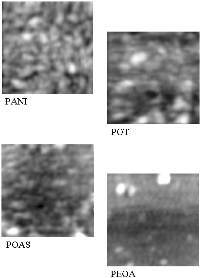
Figure 3: Atomic force microscopic pictures for
substituted polyanilines such as PANI, POT, POAS and PEOA of
1 �m x 1 �m in size.
Table 1. The results of atomic force
microscopy
| Material |
Grain Density (N/2) |
Grain Lateral size , (nm) |
The distribution of the Grains Height (nm)
|
Total grain scale corrugation (nm) |
RMS Roughness (nm) |
| PANI |
53 |
7320 |
5 - 15 |
57 |
6.9 |
| POT |
34 |
8224 |
5 - 25 |
65 |
10.2 |
| POAS |
27 |
6817 |
5 - 20 |
50 |
7.2 |
| PEOA |
19 |
8214 |
5 - 25 |
51 |
5.0 |
The numerical results shown in Table 1 are the
representative of selected images.
3.3 Electrical characterisation
The industrial application of this class of ultra thin
electro-conducting material is promising. So, the electrical
conductivity of each polyanilines LS films was studied by
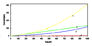
depositing on the interdigited electrodes [18, 19]. Fig.4 shows the I-V characteristics of
polyanilines films measured at a scan rate of 20 mV/sec. The
current -voltage characteristics for PANI (curve 1), POT (curve
2) and POAS (curve 3) do not show the Ohmic behaviour. It can be
related to the possible redox reaction of the interdigited
electrodes with HCl during the preparation of LB films, which
could also be related to some potential barrier with the
degenerately doped conducting polyanilines. The only curve
showing a different behaviour is that of PEOA (curve 4), with a
linear relationship in I-V characteristics. The PANI LS films
(curve 1) shows the higher magnitude of current for each measured
potential. The magnitude of current shows minimum for the PEOA LS
films. The decrease in the current magnitude in POT can be
related to the decrease in interchain order which is related to
conductivity value, whereas POAS leads to an increase in
electronic localisation and attributes to the decrease in
conductivity. Still the larger substituents group ethoxy in PEOA
shows the other effect like charge localisation along the polymer
chains which increases the orientation thus diminishing the
current (or conductivity) value.
[Full size Figure 4: 5K, 627 x 314 pixels]
Figure 4: Current -voltage characteristics of
polyanilines LS films of 40 monolayers deposited on
interdigited electrodes viz.: (1) PANI, (2) POT, (3) POAS and
(4) PEOA
3.4 Electrochemical investigation
The electrochemistry of substituted polyanilines LS films has
been investigated by cyclic voltammetry. The cyclic voltammogram
of 30 layers of each polyanilines LS films prepared at pH 1 in 1
M HCl medium is shown in Figure 5 (curves a-d).
The bias potential was swept from -0.3 to 1 V at a scan rate of
50 mV/sec. The shape of the cyclic voltammograms in Fig.5 of
curves (a-d) shows the surface confined species as expected. The
cyclic voltammetry (CVs) peaks are associated to the oxidation
and reduction processes of polyanilines LS films. These CVs
exhibits redox features characteristics of individual
polyanilines. Table 2 shows the peak
potential values of polyanilines as derived from Figure
5 (curves a-d). It means that there is a gradual decrease in
redox peak potential as a function of substituents in
polyaniline. The positive shift in the position of peak 1 is
associated to the electron transfer, which implies that the
substituent groups can induce some non-polar conformations that
decreases the conjugation along the polymer backbone, which is
responsible for the oxidation potential peak. In fact, the blue
shift in the oxidized peak potential can be related to the
decrease in the polarons/bipolarons or charged states as an
increase of substituents in polyanilines. In addition the lower
value of electrochemical reduction potential for POT (662 mV),
POAS (637 mV) and PEOA (465 mV) of LS films can also be noticed
in close comparison to the polyaniline films (at 780 mV) [27].
The change in oxidation potential value (shown in Table 2) is linked to the higher electronic
density states due to the substitution in the aromatic ring,
which facilitates the protonation and the oxidation of the amine
group. The similar results were observed for the
electrochemically grown polyanilines [27]. The middle peaks found
in POT, POAS and PEOA are variably interpreted for the formation
of quinoid like species, specifically speaking when the potential
is brought to the higher values like 1 V. The other interesting
aspect such as electrochromic effects of the films were also
observed. The electrochromism was noted from yellow to green and
later to violet as the potential was swept from -0.2 to 1.0 V for
each polyanilines conducting polymer LS films.
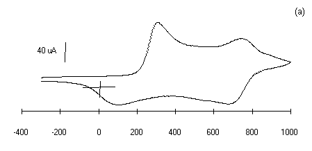 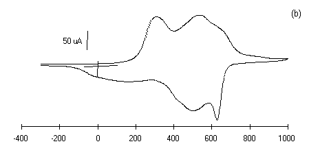 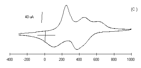 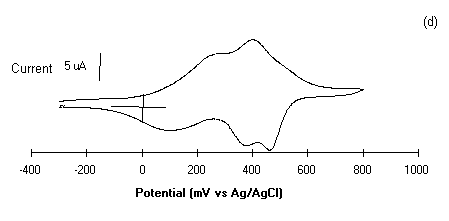
Figure 5: Cyclic voltammograms of polyanilines of
30 monolayers deposited on glass ITO plates in 1 M HCl at a
scan rate of 50 mV/sec, Viz.: (a) PANI, (b) POT, (c ) POAS
and (d) PEOA.
Table 2 The
electrochemical parameters of polyanilines
| Material |
Oxidation potential (mV) |
Reduction potential (mV) |
Charging potential (V) |
open circuit potential (V) measured after
48 hours in 1 M resistance |
| PANI |
0.78, 320 |
130, 710 |
3.0 |
1.2 |
| POT |
662, 531.8, 304 |
627.4, 499.3, 165, 23.54 |
3.0 |
1.1 |
| POAS |
707, 506, 282, |
680, 410, 144, -5.91 |
3.0 |
1.0 |
| PEOA |
563.4, 374.4, 100.5 |
401.1, 262 |
3.0 |
0.8 |
3.5 Charging and Discharging of polyanilines LS films
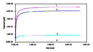
The charging and discharging on 30 monolayers containing
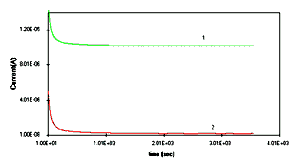
polyanilines LS films were performed in 0.01M HCl as shown in Fig.6. Polyanilines can be charged completely
nearly a time period of 15 minutes. Whereas, the discharging in
HCl can be seen as soon as there is short circuit and the
potential decreases sharply for the first instant but remains
constant for a period of one hour as shown in Fig.6b. It could be
seen that in the electrolytes containing aqueous media, it is
difficult to handle such charging and discharging phenomena.
[Full size Figure 6a: 6K, 638 x 356 pixels]
[Full size Figure 6b: 5K, 638 x 356 pixels]
Figure 6a: Charging effect for 30 monolayers LS
films of polyanilines such as (1) PANI, (2) POT, (3) POAS and
(4) POEA deposited on platinum in 0.01M HCl. Figure 6b:
Discharging effect of 30 monolayers of (1) PANI and (2) POT
films in 0.01M HCl media.
In fact, the amount of charge stored in PANI is more than the
other class of substituted polyanilines. In the substituted
polyanilines the substituents brings the hysteric hindrance which
decreases the conductivity and charge storing capacity. So we
decided to see the charging and discharging phenomenon in widely
used electrolytes i.e. LiClO4/PC. The films composed
of thirty monolayers of the polyanilines deposited on platinum
was used for the charging and discharging effect. It was first
seen that the charging of the battery at 3.0 V showed the
un-stability in the voltage value as shown in Fig.7a.
The unstability in the storage of the charge could be explained
due to the overoxidation of the polyaniline at 3.0V in LiClO4/PC
electrolytes. So, we waited for three days to see the remaining
voltage in the battery, which was found to be nearly 1.0V. Later,
the battery was charged at 1.0 V for fifteen minutes. The self
discharge was tested for three days and an interesting phenomenon
was observed. The voltage value was rising for certain amount of
time till it came to a saturation value of one volt. The charging
and discharging of the cell containing each polyanilines,
aluminium and 1M LiClO4/PC electrolytes were
performed, since there is a reversibility of the electrode
process in such electrolytes [28]. So, the doping charge is also
enhanced and saturates with time as shown in Fig.7a.
The discharging of the battery was performed by using a
resistance of 1 M and Fig.7b showed the
constant drop of voltage for a period of one day. The charging
and discharging processes of PANI LS films were shown to be same
for 10 cycles. Further, works are in progress to test the
charging and discharging cycles of such battery.
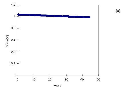
Figure 7a: Charging effect for 30 monolayers LS
films of deposited on platinum in LiClO4/PC
electrolytes with Al as another electrode.
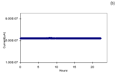
Figure 7b: Discharging effect of 30 monolayers of
PANI in LiClO4/PC electrolytes with Al as another
electrode connected to 1 M resistance which shows the
measured current.
4. Conclusions
Langmuir-Schaefer technique has been successfully applied in
obtaining the ultrathin films of various polyanilines. The
performed investigation emphasised the inclusion of HCl dopants
in the polymeric backbone, which occurs during the film formation
and indicating a different organization of polyanilines molecules
at the air/water interface. The area per molecule occupied by
molecules increases as a function of substituents in polyanilines
either studied in deionised water or pH 1. Virtually all forms of
polyanilines exhibit a microscopic structure formed from small,
nanometer-scale grains or bundles, which falls in the range of
100-800 �. The LS films of various polyanilines reveal stable
cyclic voltammetric response. The PANI LS films was found to
display better storage charge capability than the other
substituted polyanilines. We are currently pursuing the
optimization of the parameters in order to build polyanilines
based batteries.
Acknowledgements
We are thankful to Dr. Victor Erokhin and Mr. P. Faraci for
their interesting discussions during the preparation of the
manuscript. Thanks are due to Mr. D. Nardeli and Mr. A. Sardi for
their help in carrying out the experiments. Financial supports
from EL. B.A. Foundation (CAP. 2102) and Polo Nazionale
Bioelettronica are gratefully acknowledged.
References:
[1] J. J. Langer, 1990 Synth. Metals, 36, 35.
[2] A.J. Epstein and A.G. MacDiarmid in Electronic Properties
of Conjugated Polymer, Eds., H. Kuzmany , M. Mehring and S. Roth
(Springer Verlag, Berlin, 1989).
[3] E.M. Paul, A.J. Ricco and M.S. Wrighton, 1985 J. Phy.
Chem., 89, 1441.
[4] J.H. Cheung, M.F. Rubner, 1994 Thin Solid Films, 244, 990.
[5] N.E. Agbor, M.C. Petty, A.P. Monkman and H. Harris, 1993,
Synth. Metals, 55-53, 3789.
[6] G.G. Roberts, Ed. Langmuir-Blodgett Films; Plenum Press:
New York, 1990.
[7] M.F. Rubner and T.A. Skotheim, (Edited by J.L. Bredas and
R. Silbey), Conjugated Polymers, Kluwer, Amsterdam, 1991, pp
363-403.
[8] M. K. Ram, N.S. Sundaresan and B.D. Malhotra, 1993 J.
Phys. Chem., 97 11580
[9] J. H. Cheung, E. Punkka, M. Rikukawa, M.B. Rosner, A.J.
Rorappa, M.F. Rubner, 1992 Thin Solid Films, 210-211
246,
[10] A. Dhanabalan, R.B. Dabke, N. Prasant Kumar, S.S. Talwar,
S. Major, R. Lal and A.Q. Contractor, 1997, Langmuir, 13
(16) 4395-4400.
[11] A. Riul Jr., L.H.C. Mattoso, G.D. Telles, P.S.P.
Herrmann, L.A. Colnago, N.A. Parizotto, V. Baranauskas, R.M.
Faria, O.N. Oliveira Jr., 1996 Thin Solid Films, 284-285, 177.
[12] S.V. Mello, L.H.C. Mattoso, R.M. Faria and O.N. Oliveira
Jr., 1995 Synth. Metals, 71 2039-2040, Riul A. Jr.,
L.H.C. Mattoso, S.V. Mello, G.D. Telles and O.N. Oliveira, 1995 Synth.
Metals, 71 2060.
[13] M. K. Ram, S. Carrara, S. Paddeu, and C. Nicolini, 1997 Thin
Solid Films, 302, 89-97.
[14] M. Leclerc, J. Guay and L.H. Dao, 1989 Macromolecules, 22,
649.
[15] R.V. Gregory and W.C. Kimbrell, H.H. Kuhn, 1989 Synth.
Metals, 28, C-823.
[16] E.M. Scherr, A.G. MacDiarmid, S.K. Manohar, J.G. Masters,
Y. Sun, S. Tang, M.A. Druy, P.J. Glatwski, V.B. Cajipe, J.E.
Fischer, K.R. Cromack, M.E. Jozefowicz, J.M. Ginder, R.P. MacCall
and A.J. Epstein, 1989 Synth. Met., 25 649.
[17] J. Pellerino, R. Radebaugh and B.R. Mattes, 1996 Macromolecules,
29 4985.
[18] M.K. Ram, S. Paddeu, S. Carrara, E. Maccioni and C.
Nicolini, 1997 Langmuir, .13, (10), 2760-2765,
[19] S. Paddeu, M.K. Ram and C. Nicolini, 1997 J.
Phys. Chem.B, 101 4759-4766.
[20] M.K. Ram, E. Maccioni and C. Nicolini, 1997 Thin Solid
Films, 303 27-33.
[21] S.P. Armes and J.F. Miller, 1986 Synth. Metals, 13,
193.
[22] H. Bleier, J. Finter, B. Hilti, W. Hofherr, C.W. Mayer,
E. Minder, H. Hediger and J.P. Anssermet, 1993 Synth. Metals,
55-57, 3605 - 3610.
[23] A.G. MacDiarmid, J.C. Chiang, A.F. Richter, N.L. D.
Somasiri and A.J. Epstein, In: Conducting polymers, (Edited by
Luis Alcacer), Riedel Publ., Dordrecht, Holland, 1987, pp
105-120.
[24] G. Binnig, C.F.Quate, Ch. Gerber, 1986 Phys. Rev. Lett., 56
930.
[25] M. Ando, Y. Watanabe, T. Iyoda, K. Honda and T. Shimidzu,
1989 Thin Solid Films, 178, 373.
[26] T.L. Porter, D. Thompson and M. Bradley, 1996 Thin Solid
Films, 288, 268-271.
[27] E. W. Paul, A.J. Ricco and M.S. Wrighton, 1985 J.
Phys. Chem., 89 1441.
[28] Y. Echigo, K. Asami, H. Takahashi, K. Inouue, T. Kabata,
O. Kimura and T. Ohsawa, 1993 Synth. Metals, 55-57
3611-3616.
|