Nanostructured Chiral Surfaces
by
K.-H. Ernst*, a,
M. Böhringera, C. F. McFaddena, P. Huga, U. Müllera,U. Ellerbeckb
aSwiss Federal Laboratories
for Materials Testing and Research (EMPA)
Surface Technologies,
Ueberlandstrasse 129, CH-8600 Dübendorf, Switzerland
bDepartment of Food Toxicology, Veterinary Medical
University of Hannover, Germany
*Ccorresponding author: [email protected]
Web page: http://www.empa.ch/englisch/fachber/abt124/staff/ekh.htm
This is a draft paper for a talk at the
Sixth
Foresight Conference on Molecular Nanotechnology.
The final version has been submitted
for publication in the special Conference issue of Nanotechnology.
Abstract
A method for generating stable nanostructured thin films and surfaces is proposed. The chiral surfaces will be fabricated in a two-step process in which an achiral substrate is first modified by the adsorption of one enantiomer of a helical molecule. This will provide a chiral matrix for subsequent physical vapor deposition (PVD) of metals. It is expected that the helical molecules will serve as nucleation sites for the formation of screw dislocations. All steps of the fabrication are performed in ultrahigh vacuum (UHV) and monitored in-situ with scanning tunnelling microscopy (STM). As the organic chiral matrix, a closed packed monolayer of heptahelicene, a aromatic hydrocarbon, on a nickel(111) surface was generated. The investigation on the structure of this matrix as well as first results of its influence on the structures of subsequently deposited palladium and copper layers are reported.
Introduction
Chiral Surfaces
Since the first observed catalytic stereospecifity of a chiral quartz substrate [Schwab32,Schwab34], chiral surfaces have been of interest in applications such as stereoselective chemical synthesis, separation of chiral compounds, crystal growth, protein adsorption, and optical activity. Therefore, studying the adsorption and reaction of chiral molecules on well-characterized chiral surfaces in UHV will provide a framework for understanding the mechanism of stereoselective interaction of molecules with surfaces.
Chiral surfaces are predicted to have outstanding nonlinear optical activity. Raman and Rayleigh scattering were calculated to be three orders of magnitudes larger than from bulk material [Hecht94]. Also a large circular difference response of second harmonic generation (or second harmonic optical activity, SHOA) was measured on chiral surfaces [Byers94, Verbiest94].
With the increasing application of scanning probe techniques in thin film deposition, the formation of screw dislocations and "spiral-layer-growth" is often observed [Schlom92]. On an achiral substrate there is equal probability to form left- or right-handed screw dislocations. For generating films consisting of screw dislocations with the same handedness an asymmetric element must be introduced, for example by a chiral substrate onto which the deposition process is performed. Two possibilities of such substrates are (Fig 1):
- a two-dimensional overlayer of chiral molecules and
- a well-prepared crystal plane of an enantiomorphic mineral, e.g. b-quartz.
A third possibility for preparation of solid chiral films, namely beam deposition onto rotating substrates, was suggested by Azzam [Azzam92].
In this paper we focus on the first method - the deposition of
metal films onto a closed-packed layer of chiral molecules.
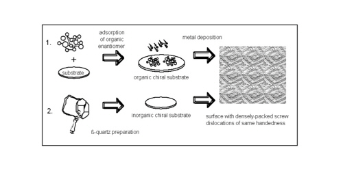
Fig.1: Chiral substrates serving as matrices for generating metallic layers with screw dislocations of the same handedness.
The Chiral Molecule
As a promising precursor molecule, we chose heptahelicene, C30H18, a polyaromatic phenanthrene derivative (Fig. 2). The reasons for this choice were:
- The molecule has a helical structure and is aromatic. Aromatic molecules are known to form stable complexes with transition metals, so it is expected that it has good "nucleation power" for screw dislocations.
- Compared to other carbohelicenes, its enthalpy for thermal racemization (167 kJ/mol in solution [Martin74]) is sufficiently high to survive sublimation.
- The synthesis is somewhat easier than those of the higher helicenes. Heptahelicene was first synthesized in 1967 from stilbene derivatives via photo cyclo dehydrogenation [Flammang-Barbieux67].
- Numerous studies of aromatic molecules (e.g. benzene, naphtalene, coronene, perylene) on well-defined metal single crystal surfaces and on highly oriented pyrolytic graphite (hopg) showed that these molecules are adsorbed in a geometry with the benzene rings parallel to the surface [Netzer91, Netzer92]. Therefore, is expected that the helicene molecule will also adsorb with one or two aromatic rings oriented parallel to the surface, leading to a geometry where the molecule spirals away from the surface.
Fig.2: Model of M-heptahelicene
Experimental
We synthesized racemic heptahelicene as described previously [Sudhakar86]. The separation of the enantiomers was accomplished via high-performance liquid chromatography (HPLC) [Mikes78]. The chromatogram showed the perfectly resolved enantiomers. However, with each run only an amount of about 100 µg of the pure enantiomers could have been obtained. Their enantiomeric purity was controlled by a subsequent HPLC analysis showing only one peak. The absolute assignment of the enantiomers (M-, for minus and P-, for plus) was done by comparison of our acquired CD-spectra with those from the literature, where in turn the M- and P-heptahelicene were assigned with the help of x-ray crystallography [Martin74].
All steps of the fabrication were performed in ultrahigh vacuum (UHV, base pressure p = 2 x 10⁻⁸ Pa) and monitored in-situ with scanning tunneling microscopy (STM) at room temperature. The room-temperature-STM (Physical Electronics, PHI) was driven by a Nanoscope controller.
The formation of a closed packed helicene overlayer was also controlled with methods like temperature programmed desorption (TPD), x-ray photoelectron spectroscopy (XPS), photoelectron diffraction (PD), low energy electron diffraction (LEED), time-of-flight secondary ion mass spectrometry (ToF-SIMS), and Auger electron spectroscopy (AES). X-ray absorption spectroscopy (NEXAFS) studies were performed at the Berlin Storage Ring for Synchrotron Radiation (BESSY I), Germany. The helicene deposition was performed with a home-made knudsen cell as described in [Holtkamp84]. For the deposition of palladium and copper onto the helicene layer, commercial effusion cells were used. The deposition rates of both metals were calibrated via a quartz micro balance. The nickel single crystal was purchased at Monocrystals Company, Richmond Heights, Ohio, USA.
Results and Discussion
The Chiral Matrix: M- or P-heptahelicene on Ni(111)
Only after the complete characterization of the organic matrix, conclusions on its influence on the structure of the subsequently deposited metal layers can be made. The complete investigations on the interaction of racemic heptahelicene as well as the pure enantiomers with the (111)-surfaces of nickel and copper single crystals will be published in much greater detail elsewhere.
The aim of these investigations was to find out, if...
- the molecule is adsorbed intactly.
- the "spiral" stands on the surface, i.e. what is the local adsorbate geometry?
- a closed packed layer is formed with small intermolecular distances between the molecules.
The first question could have been answered via the ToF-SIMS method. In a ToF-SIMS experiment the surface is bombarded with cesium ions. This causes the formation of secondary ions which can be detected in a time-of-flight mass spectrometer.
The spectra acquired from heptahelicene layers at coverages up to one monolayer were dominated by masses corresponding to heptahelicene-Ni+-cluster. Signals corresponding to the heptahelicene-Ni+2-clusters and the molecular mass were detected as well. From this follows that the helicene is not decomposed on Ni(111) under these conditions. The assignment of these signals were supported by the observation of the expected isotopic ratios for the clusters.
The determination of the local adsorbate geometry was performed via x-ray absorption spectroscopy, in particular by analysis of the "Near Edge X-ray Absorption Fine Structure" (NEXAFS). Utilizing symmetry selection rules of the absorption of linearly polarized light one can determine the relative orientation of molecular orbitals with respect to the plane of polarization of the x-ray radiation. That is, an exitation of carbon 1s electrons into unoccupied PI-orbitals - and therefore x-ray absorption as well - will show maximum intensity, when the electric field vector of the incomming light is parallel to the PI-orbitals of the molecules. Thus, by variation of the angle of incidence of the radiation and measuring the intensity of the PI-resonances in the spectra, one can determine the direction of a molecular axis with respect to the surface.
As expected, the NEXAFS studies showed that the PI-orbitals are perpendicular to the surface, i.e. the first C6-ring is parallel to the surface or: the heptahelicene molecule "stands upright" on the surface (Fig. 3).
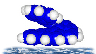
Fig. 3: Illustration of the molecular orientation on the surface.
The formation of a laterally ordered heptahelicene layer was at first investigated with low energy electron diffraction (LEED). At monolayer coverage and room temperature rings around the substrate diffraction spots were observed. This indicated a certain long range order, but not a perfect superstructure. The radius of the rings were about 1/4 of the reciprocal substrate lattice vector.
Figure 4 and Fig. 5 show STM images of heptahelicene molecules on the surface at two different coverages. Every bright dot is representative for one molecule. This conclusion is based on the linear dependence of the number of bright dots with time of exposure to the molecular beam. Furthermore, thermal desorption of heptahelicene made the dots disapear, and finally the dimension of one "dot" is roughly identical with the molecular dimension of heptahelicene.
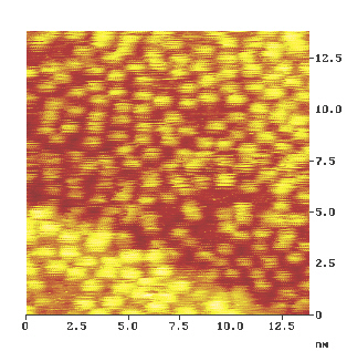
Fig.4: STM image of heptahelicene molecules at sub monolayer coverage (2/3 of the closed packed monolayer).
At sub monolayer coverage there is no lateral order of the molecules on the surface. However, at one monolayer coverage the molecules are squeezed together and form a two-dimensional hexagonal lattice (Fig. 5). The intermolecular distances are 1 nm, which is exactly in the desired range. Very interestingly, Fig. 5 shows another detail. Although atomic resolution on the subtrate is reached at the atomic steps of the terrace edges, no intramolecular details are revealed. Changing the tunnelling parameter, like bias and tunnel current did not result in a better intramolecular resolution.
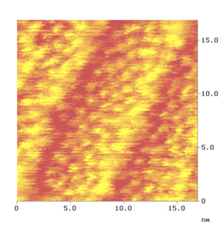
Fig. 5: STM-image of the ordered hepta- helicene layer. At the step-edge atomic resolution of the substrate is observed as well.
Copper and Palladium Deposition
These first results of the experiments focus on the influence of different metals on the structure of the grown layers.
Fig. 6 shows a wider range scan on the closed-packed heptahelicene layer onto which the depositions of the metals were performed. It is obvious that the surface is stepped. This is due to a misalignment of about one degree during the preparation of the nickel(111) surface. Every terrace is only 6 to 10 nm wide.
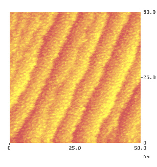
Fig. 6: The organic matrix before metal deposition.
However, this fact helps us to visualize the differnce in copper and palladium deposition. The result is thown in Fig. 7. In both cases the equivalent of about five monolayers of palladium and copper were deposited (one monolayer corresponds to a number of about 1 . 1019 atoms . m-2). Deposition of copper (Fig. 7, top right and bottom right) does not dramatically change the width of the terraces. The density stays roughly the same. However, their edges are not parallel anymore when compared to the nickel substrate. The shape of the terraces become spherical. In the case of palladium (Fig. 7, top left and bottom left) a dramatic change of surface morphology is observed. A much higher density of steps is generated. The edges still run parallel although they are more fringed than on the substrate and in the case of copper deposition.
We believe, that this effect is due to the higher affinity of palladium to aromatic compounds, namely the tendency of the formation of PI-complexes. However, our first results do not allow more conclusions. Because the steps have a major impact on the growth process of metal layers, data from single crystal surfaces with terrace width of at least 100 nm must be available.
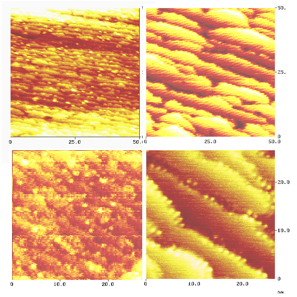
Fig. 7:The surface after palladium (images left) and copper (images right) deposition.
The surfaces show after metal deposition bright dots as well. However, unless Tof-SIMS experiments on the deposited metal layers show again the presence of the helicene molecules, we are not confident enough to assign these bright "dots" to the matrix molecules.
Summary and Conclusions
The most important prerequisites for serving as a nanostructured chiral matrix were fulfilled for the system P- or M-heptahelicene on Ni(111). It has been shown that heptahelicene adsorbes without decomposition and forms a regular closed packed monolayer. The distances between the helical molecules are one nanometer. The molecule "spirals" perpendicular with respect to the surface. However, the preparation of chiral surfaces via metal deposition requires perfect substrates, i.e. single crystal surfaces. Nevertheless, substantial differences in the morphology of deposited copper and palladium layers were observed.
Future Experiments
Currently, we set up an experiment for testing the organic chiral matrix for circular dichroism in nonlinear optical responses (e.g. circular dichroism in second harmonic generation, SHOA). This will be performed on the metallic chiral surfaces, once produced, as well. It is also considered to fabricate chiral metal-organic matrix compounds by depositing sandwich layers via molecular beam epitaxy of metals and helical molecules.
Acknowledgements
Financial support by the Schweizer Nationalfonds (NFP 36 4036-043974) is
gratefully acknowledged. C.F.M. thanks the US-National Science Foundation (NSF)
for an International Post-Doctorial Research Fellowship.
References
- [Schwab32] G. M. Schwab, L. Rudolph, Naturwiss. 20 (1932) 363.
- [Schwab34] G. M. Schwab, F. Rost, L. Rudolph, Kolloid-Zeitschrift 68 (1934) 157,
- [Hecht94] L. Hecht, L. Barron, Rayleigh and Raman optical activity from chiral surfaces, Chem. Phys. Lett. 225 (1994) 525.
- [Byers94] J. D. Byer, H. I. Yee, T. Petralli-Mallow, J. M. Hicks, Second harmonic generation circular-dichroism spectroscopy from chiral monolayers, Phys. Rev. B 49 (1994) 14643.
- [Verbiest94] T. Verbiest, M. Kauranen, A. Persoons, M. Ikonen, J. Kurkela, H. Lemmtyinen, Nonlinear optical activity and biomolecular chirality, J. Am. Chem. Soc. 116 (1994) 9203.
- [Schlom92] D.G. Schlom, D. Anselmetti, J.G. Bednorz, R.F. Broom, A. Catana, T. Frey, Ch. Gerber, H.-J. Güntherodt, H.P. Lang, J. Mannhart, Z. Phys. B - Condensed Matter 86 (1992) 163 (and refs. therein).
- [Azzam 1992] Chiral thin solid films: method of deposition and applications, Appl. Phys. Lett. 61 (1992) 3118.
- [Martin74]R.H. Martin, M.J. Marchant, Tetrahedron 30 (1974) 374.
- [Netzer91] F. Netzer, Surface structure and reactivity of organic molecules, Langmuir 7 (1991) 2544,
- [Netzer92] F.Netzer , M.G. Ramsey, Critical Reviews in Solid State and Materials Sciences 17 (1992) 397.
- [Flammang-Barbieux67] M. Flammang-Barbieux, J. Nasielski, R.H. Martin, Tetrahedron Letters (1967) 743.
- [Sudhakar86] A. Sudhakar, T.J. Katz, Tetrahedron Letters 27 (1986) 2231.
- [Mikes78] F. Mikes, G. Boshart, J. Chromatography 149 (1978) 455.
- [Holtkamp84] D. Holtkamp, W. Lange, M. Jirikowsky, A. Benninghoven, UHV preparation of organic overlayers by a molecular beam technique, Appl. Surface Sci. 17 (1984) 296.
|