Engineering of Nanostructures
from Carbon Nanotubules
by
A. Garg and S. B. Sinnott*
Department of Chemical and Materials
Engineering
The University of Kentucky
Lexington, Kentucky 40506-0046
*Email: [email protected]
This is a draft paper
for a talk at the
Fifth
Foresight Conference on Molecular Nanotechnology.
The final version has been submitted
for publication in the special Conference issue of Nanotechnology.
This page uses the HTML <sup> and <sub>
conventions for superscripts and subscripts. If "103"
looks the same as "103" then your browser does not
support superscripts. If "xi" looks the
same as "xi" then your browser does not support
subscripts. Failure to support superscripts or subscripts can
lead to confusion in the following text, particularly in
interpreting exponents.
Abstract
Proximal probe technology has provided researchers with new
ways to investigate and manipulate matter on the nanometer scale.
We have studied, through molecular dynamics simulations, using a
many-body empirical potential, the indentation of a
hydrogen-terminated, diamond (111) surface, with a proximal probe
tip that consists of an open, hydrogen-terminated, (10,10) carbon
nanotubule. The simulations showed that upon indenting 1.8 �,
the tubule deforms but returns to its original shape upon
retraction. The Young�s modulus of the tubule was determined
using the predicted Euler buckling force and was found to be
comparable to measured and calculated values. In a second series
of simulations, an open (10, 10) nanotubule was heated to
4500 K and allowed to close. We find that at this
temperature the resulting cap contains numerous imperfections,
including some not mentioned previously in the literature.
Introduction
Advances in proximal probe technology over the last decade
have given researchers new abilities to investigate, process and
manipulate matter at the nanometer scale, where material
properties can be significantly different from the bulk. As this
fascinating new realm of nanometer-scale materials engineering
continues to be explored and understood, our ability to
manufacture powerful new devices will increase. Current
experimental efforts have focused on using proximal probes such
as the Atomic Force Microscope (AFM) to study the nanometer-scale
properties of thin films and substrates1 and
manipulate individual atoms in an effort to create
nanometer-scale structures and switches.2,3,4,5,6
Theoretical efforts have concentrated on providing information
about the mechanisms involved in microscope tip-surface
interactions7,8,9,10,11 and exploring new applications
and materials not yet available for experimental study.12,13
During much of the same time period, there has also been
intense interest in a new class of materials known as carbon
nanotubules. Since their discovery by Iijima,14 they
have been under concentrated study by numerous research groups.15
Carbon nanotubules, which may be thought of as rolled up sheets
of graphite, can have different helical structures and can be
single-walled (SWT) or multi-walled (MWT).14,16 In the
latter case, 2-50 tubules can be positioned concentrically within
one another. Changes in the helical structure and diameter can
affect the overall electronic properties of nanotubules which
range from semiconducting to metallic.17,18,19 There
has also been considerable interest in the mechanical properties
of carbon nanotubules because of their predicted20,21,22,23,24,25
and measured26,27 high modulus in the direction of the
tubule axis.
Recently, Smalley and co-workers have attached individual
carbon nanotubules to silicon cantilevers in conventional AFM
instruments.28 This is an important advancement in
proximal probe microscopy because such tips can not only conduct,
they should also be resistant to mechanical damage while at the
same time providing superior imaging capabilities due to their
relative sharpness. Although only briefly mentioned by Smalley
and coworkers, such tips, will be important in nanometer-scale
AFM measurements because of the well-defined contact area between
the tip and the sample.
Over the last few years there has been much discussion in the
literature about the mechanisms by which nanotubules form under
various conditions, such as in the presence of metal catalysts
like iron to produce SWTs.29 For example, Charlier et
al. have performed first principles molecular dynamics (MD)
simulations of the closure of (10, 0) and (5, 5) tubules at about
3000 K and have shown that the closed (10, 0) tubule is more
stable than the open tube by about 18 eV.30 (see
Ref. 15 or 21 for a discussion of these reference numbers). In
addition, these simulations provided researchers with a glimpse
into the atomic-scale mechanisms by which tubules might close.
This paper examines, through MD simulations using a
well-known, classical, empirical, many-body potential, the
indentation of a hydrogen-terminated, diamond (111) surface,
C(111):H, with an AFM tip which has as its tip an open,
hydrogen-terminated, (10,10) carbon nanotubule. We also replicate
the simulations of Charlier et al. with this classical potential
using a larger tubule system.
Methodology
The MD simulations integrate Newton�s equations of motion
using a third-order Nordsieck predictor-corrector method31
with a time step of 0.15 fs. In this approach the forces on
the individual carbon atoms are determined from an improved
reactive-empirical bond order (REBO) hydrocarbon potential that
realistically characterizes the properties of small hydrocarbon
molecules, graphite and diamond.32 This potential
includes improved analytic functions for intramolecular
interactions and an expanded fitting database, which includes
radicals, small hydrocarbon molecules, graphite and diamond.
Because the atoms are treated as hard spheres, forces from
electronic effects like orbital resonance and symmetry are
neglected. In addition, since this potential is comparatively
short ranged, long-ranged forces, like H-bonding, are not
included.
The potential predicts elastic constants for diamond of c11=10.78
x 1011 N/m2, c12=1.31 x 10¹¹
N/m2 and c44=6.8 x 10¹¹ N/m2
which compare favorably with the respective experimental values
of c11=10.76 x 10¹¹ N/m2, c12=1.25
x 1011 N/m2 and c44=5.8 x 10¹¹
N/m2.33 It has been successfully used to
simulate numerous processes including the deformation of carbon
nanotubules,21,24,25 the indentation of diamond
surfaces7,10 and amorphous carbon thin films,12,16
surface patterning,12,13 nanofriction and
tribochemistry,34 ion-bombardment of polymers,35
the formation of fullerenes from graphitic ribbons,36
and surface chemical reactions.37,38,39,40
Results and Discussion
A. Indentation of C(111):H with a SWT
The carbon nanotubule used for the indentation simulation is
of type (10,10) and consists of 20 unit cells, terminated with 10
hydrogen atoms at each end for a total of 820 atoms in the tip.
The C(111):H surface is composed of 20 layers of carbon with each
layer containing 370 atoms. Periodic boundary conditions are
applied in the plane of the surface and both end layers of the
substrate are hydrogen terminated (370 atoms). Thus the substrate
contains 8140 atoms and the entire system consists of 8960 atoms.
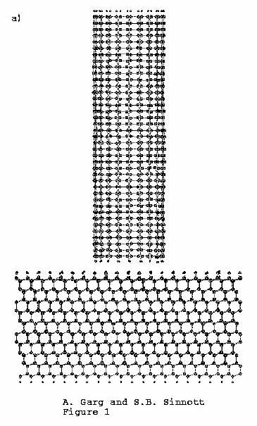
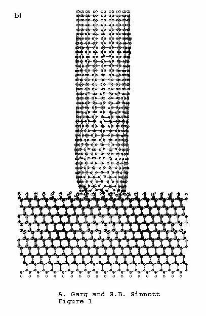
The indentation sequence is shown in Figure 1, where Figure 1(a) shows the initial
configuration. The top 100 atoms of the carbon nanotubule
(furthest from the surface) and the 1480 atoms at the base of the
substrate (furthest from the tip) are held rigid throughout the
simulation. Moving toward the middle of the system, a Langevin
thermostat31 is applied to the next 200 atoms of the
nanotubule and 2590 atoms of the substrate. The remaining atoms
of both the nanotubule and the substrate evolve in time according
to Newton�s equations of motion with no constraints. The
simulation is carried out at 300 K.
The rigid atoms at the end of the nanotubule are moved towards
the substrate in steps of 0.05 � and the system is equilibrated
for 400 time steps in between displacement steps. This process is
continued until the nanotubule indents the substrate about
1.8 �. After indentation, the tip is retracted using
identical displacement and time steps. The force on the tip atoms
is calculated at each time step. To minimize fluctuations in the
force caused by the relaxation of the atoms, the forces are
averaged over the last 100 time steps.
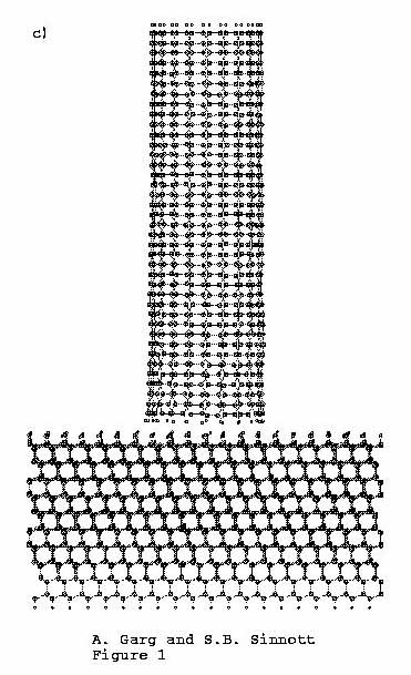
As the indentation proceeds, the tip compresses along and then
deforms slightly at the end that is in contact with the C(111):H
surface (Figure 1(b)). After
retraction (Figure 1(c)), the
nanotubule and substrate both return to their starting
configurations.
Figure 1. C (111):H substrate is indented
by (10, 10) carbon nanotube tip. (a)
Time = 0.00 ps, (b) time
= 4.37 ps, (c) time =
8.57 ps.
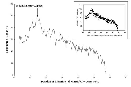
In a second simulation, the indentation was continued until
the nanotubule deformed plastically through a buckling mechanism,
thus reducing the load on the tip (Figure
2). Figure 2 (inset) shows that the force on the tip atoms
increases almost linearly with the displacement of the nanotubule
and that the maximum force felt by the tip is approximately 100
nN, before the onset of buckling. This force is the Euler
buckling force.23
 Eq. 1. Eq. 1.
where I is the stress moment over the cross section of the
nanotubule radius (I � p r4/4).28 The radius
(r) and the length (L) of the carbon nanotubule are 6.78 �
and 47.8 � respectively. Using Eq. (1) we determined the
Young�s modulus of the tubule tip to be 1394 GPa. This
calculated Young�s modulus shows excellent agreement with
previous theoretical estimates for SWTs of 1400-5500 GPa.22,23
The experimentally determined average value for MWTs was found to
be 1800 GPa,27 which also shows good agreement
with the calculated value.
The Euler buckling force varies with changes to the length of
the tube. In other words, increasing the length of the nanotubule
tip will result in a gentler probe that can be pushed against a
softer surface without damaging it, though the modulus of the
tube will not change. Hence, our system can be directly compared
to the system examined by Smalley and co-workers28
with a tip that was approximately 6 m
m long and buckled at a load of about 5 nN. They assumed a
modulus of about 1000 GPa.
Figure 2. Force on the carbon nanotube
versus the distance from the top of the tip to the substrate.
Only the loading portion of the curve is shown. The inset
shows best fit linearity to the data.
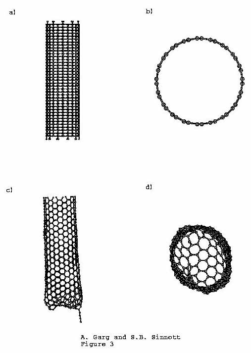
B. Closure of the Carbon Nanotubule
The closure of a (10,10) "armchair" carbon
nanotubule that has 10 single bonded carbon atoms at the ends is
considered in these simulations. The nanotubule again consists of
20 unit cells (800 atoms) as shown in Figure
3. 130 atoms at one end of the nanotubule are held rigid
throughout the simulation. Moving towards the middle of the
tubule, a Langevin thermostat is applied to the next 280 atoms.
The remaining atoms evolve in time according to Newton�s
equations of motion with no constraints.
The simulations are carried out at temperature of 4500 K.
The open end of the nanotubule is allowed to relax for
72.1 ps followed by cooling to 300 K at the rate of
1 K/fs (Figure 3). As simulation progresses, the atoms at
the end of the nanotubule move to come together, thus closing the
end. By the end of the simulation, the closed end consists of 8
pentagons, 10 heptagons, 6 two-coordinate carbon atoms and 1
one-coordinate carbon atom (3 two-coordinate carbon atoms and 1
one-coordinate carbon atom are in the chain hanging at the closed
end). The number of heptagons is high due to the presence of the
3 two-coordinate carbon atoms, which results in a closed end that
is not perfectly hemispherical. The REBO potential predicts that
an ideally closed (10,10) tubule is more stable than an
open-ended (10,10) tubule by about 0.53 eV/atom, for the system
of 150 carbon atoms. However, due to the large number of
imperfections, the closed tubule from the simulation described
above does not gain this much energy.
Figure 3. Initial and final views of the
(10, 10) nanotubule at 4500 K. (a) Initial front view, (b)
Initial top view, (c) Final front view (rotated to show chain
attachment), (d) Final top view.
Allowing the nanotubule to relax for nano- or micro-second
time scales might decrease the number of imperfections in the
tubule. However, these time scales are not accessible in these
simulations, which are restricted to relaxation times of the
order of hundreds of ps.
Charlier et al. have predicted through first principles
simulations that for a (10, 0) tubule the closed structure is 1.8
eV/atom more stable than the open structure. This difference is
most likely due to the higher accuracy of the first principles
approach. Hence, while the REBO correctly predicts qualitative
trends, it does not match the quantitative accuracy of density
functional theory.
Conclusions
We have shown through classical molecular dynamics simulations
the atomic-scale mechanisms by which a tubule tip would respond
during the indentation of a hydrogen-terminated diamond (111)
surface. The Young�s modulus for the nanotubule was determined
to be 1394 GPa, which is in good agreement with previous work. We
have also studied the closing of nanotubules at 4500 K and
compared our results to first principles simulation results.
Acknowledgments
The authors gratefully acknowledge the support of NASA Ames
Research Center (Grant Number NAG 2-1121).
References
- Burnham N. A. and Colton R. J., 1989 J. Vac. Sci.
Technol. A 7, 2906.
- Salling C. T., 1996 J. Vac. Sci. Technol. B 14,
1322.
- Becker R. S., Golovchenko J. A., and Swartzentruber B.
S., 1987 Nature, 325, 419.
- Lyo W., and Avouris Ph., 1991 Science, 253, 173.
- Uchida H., Hwang D., Grey F., and Aono M., 1993 Phys.
Rev. Lett. 70, 85.
- Eigler D. M., and Schweizer E. K., 1990 Nature, 344,
524.
- Sinnott S. B., Colton R. J., White C. T., Shenderova O.
A., Brenner D. W. and Harrison J. A., 1997 J. Vac. Sci.
Technol. A 15, 936.
- Landman U., Luedtke W. D., Burnham N. A., and Colton R.
J., 1990 Science 248, 454.
- Harrison J. A., and Brenner D. W., in The Handbook of
Micro/Nanotribology, edited by B. Bhushan (Chemical
Rubber, Boca Raton, Florida, 1995), and references
therein.
- Harrison J. A., White C. T., Colton R. J., and Brenner D.
W., 1992 Surf. Sci. 271, 57; Harrison J. A.,
Colton R. J., White C. T., and Brenner D. W., 1992 Mater.
Res. Soc. Symp. Proc. 239, 573.
- Glosli J. N., Philpot M. R., and Belak J., 1995 Mater.
Res. Soc. Symp. Proc. 383, 431.
- Sinnott S. B., Colton R. J., White C. T., and Brenner D.
W., 1994 Surf. Sci. 316, L1055.
- Brenner D. W., Sinnott S. B., Harrison J. A., and
Shenderova O. A., 1996 Nanotechnology 7, 1.
- Iijima S., 1991 Nature 354, 56.
- See, for example, Ebbesen T. W., Physics Today, 26 (June,
1996); Chemical Engineering Progress 17 (March,
1997).
- Ebbesen T. W., and Ajayan P. M., 1992 Nature 358,
220.
- Mintmire J. W., Dunlap D. I., and White C. T., 1992 Phys.
Rev. Lett. 68, 631.
- Saito R., Fujita M., Dresselhaus G., and Dresselhaus M.
S., 1992 Phys. Rev. B 46, 1804.
- Hamada N., Sawad S., and Oshiyamu A., 1992 Phys. Rev.
Lett. 68, 1579.
- Overney G., Zhong W., and Tomanek D., 1993 Z. Phys. D 27,
93.
- Robertson D. H., Brenner D. W., and Mintmire J. W., 1992
Phys. Rev. B 45, 12592.
- Molina J. M., Savinsky S. S., and Khokhriakov N. V., 1996
J. Chem. Phys. 104, 4652.
- Yakobson B. I., Brabec C. J., and Bernholc J., 1996 Phys.
Rev. Lett. 76, 2511.
- Sinnott S. B., Shenderova O. A., White C. T., and Brenner
D. W., Carbon (in press); Sinnott S. B., White C. T., and
Brenner D. W., in Science and Technology of Fullerene
Materials, Eds. Bernier P., Buthune D. S., Chiang L. Y.,
Ebbesen T. W., Metzger R. M. and Mintmire J. W., MRS
Symposia Proceedings No. 359 (Materials Research Society,
Pittsburgh, PA, 1995), pp. 241.
- Cornwell C. F. and Wille L. T., 1997 Solid State Commun. 101,
555.
- Ajayan P. M., Stephan O., Colliex C. and Trauth D., 1994
Science 265, 1212.
- Treacy M. M. J., Ebbesen T. W., and Gibson J. M., 1996
Nature 381, 678.
- Dai H.,
Hafner J. H., Rinzler A. G., Colbert D. T. and Smalley R.
E., 1996 Nature 384, 147.
- Iijima S. and Ichihashi T., 1993 Nature, 363, 603.
- Charlier J. �C., De Vita A., Blas� X. and Car R., 1997
Science 275, 646.
- Allen M. P. and Tildesley D. J., Computer Simulation
of Liquids, Oxford University Press, New York, 1987.
- Brenner D. W., Sinnott S. B., Shenderova O. A. and
Harrison J. A. (unpublished); Brenner D. W., 1990 Phys.
Rev. B 42, 9458.
- Grimsditch M. H., and Ramadas A. K., 1975 Phys. Rev. B 11,
3139.
- Perry M. D. and Harrison J. A., 1996 Langmuir 12,
4552; Perry M.D. and Harrison J. A., J. Chem. Phys. B 101,
1364 (1997); Harrison J. A. and Brenner D. W., 1994 J.
Am. Chem. Soc. 116, 10399.
- Brenner D. W., Shenderova O. A. and Parker C. B., 1997
MRS Res. Symp. Proc. 438, 491.
- Robertson D. H., Brenner D. W. and White C. T., 1992 J.
Phys. Chem. 96, 6133.
- Williams E. R., Jones, G. C. Jr., Fang L., Zare R. N.,
Garrison B. J. and Brenner D. W., 1992 J. Am. Chem. Soc. 114,
3207.
- Qi L. and Sinnott S. B., 1997 J. Phys. Chem. B 101,
6883; Qi L. and Sinnott S. B., Surf. Sci. (in press).
- Brenner D. W. and Harrison J. A., 1992 Ceramic Bulletin 71,
1821.
- Peploski J., Thompson D. L., and Raff L. M., 1992 J.
Phys. Chem. 96, 8539; Chang X. Y., Thompson D. L.,
and Raff L. M., 1993 J. Chem. Phys. 100, 1765.
|